Series And Parallel Circuits : Combined Series Parallel Circuits Read Physics Ck 12 Foundation : Series circuits are useful if you want a warning that one of the components in the circuit has failed.
Series And Parallel Circuits : Combined Series Parallel Circuits Read Physics Ck 12 Foundation : Series circuits are useful if you want a warning that one of the components in the circuit has failed.. How to solve resistors in series circuits. There are two basic types of electrical circuits; Series and parallel describes two different types of circuit arrangements. While in a parallel circuit, the multiple components are connected in head to head and tail to tail orientation. Much more common than series circuits are those wired in parallel—including most household branch circuits powering light fixtures, outlets, and appliances.
Hand out the series and parallel circuits worksheet, as well as some sheets of paper for sketching designs. You will discover how meticulously the teachers have described the concepts of series connection, parallel connection, and their differences. The parallel circuits are particularly good practice and the exercise will reinforce their understanding that ammeters must be connected in series and voltmeters in parallel. In series circuits, current is constant throughout the loop so that you can measure a single component's current in a series circuit to determine the current of all the circuit's elements. While in a parallel circuit, the multiple components are connected in head to head and tail to tail orientation.
Series Parallel Circuits from weblab.deusto.es Series and parallel circuit methods. The series circuit is one that only has one path for the current to flow through. You may have noticed the differences in electrical circuits you use. And the more work you have a series circuit do, the more your current will decrease. Series and parallel circuits function differently. The resulting electrical network will have two terminals, and itself can participate in a series or parallel topology. Up until now, we have only been looking at simple circuits. While in a parallel circuit, the multiple components are connected in head to head and tail to tail orientation.
It contains plenty of examples, equations, formulas, and practice problems showing you.
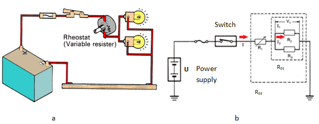
A circuit in which two of more electrical resistances or loads are connected across the same voltage source is called a parallel circuit. The parallel circuits are particularly good practice and the exercise will reinforce their understanding that ammeters must be connected in series and voltmeters in parallel. One from 1 to 2 to 5 to 6 and back to 1 again series and parallel resistor configurations have very different electrical properties. In figure 2's circuit the battery is providing 10v. Voltage drops in series circuits. Components in a circuit can be connected in series or in parallel. In this circuit, we have two loops for the current to flow through: In parallel circuits different components are connected on different branches of the wire. In series circuits, current is constant throughout the loop so that you can measure a single component's current in a series circuit to determine the current of all the circuit's elements. Series and parallel arrangements are two basic configurations in which we can arrange the electrical components. They also use less wiring than parallel circuits. In series circuit it follows that if there is a break in any part of the circuit, no current flows.this is why fuses, circuit breakers and safety switches are placed in series with i've provided below a schematic diagram of a typical series circuit and parallel circuit, to illustrate the difference between the two. You may have noticed the differences in electrical circuits you use.
There are two types of circuits; Voltage drops in series circuits. In this circuit, we have two loops for the current to flow through: The current flowing through these circuits remains same at any point but the voltage varies. Up until now, we have only been looking at simple circuits.
Student S Radio Physics Course Series And Parallel Circuits July 1932 Radio News Rf Cafe from www.rfcafe.com Series and parallel circuits function differently. How series and parallel circuits differ pg. If you follow the circuit diagram from one side of the cell. Series connected circuits consist of two or more active and/or passive devices connected in series. Examine the example circuit, below. Series and parallel arrangements are two basic configurations in which we can arrange the electrical components. We also need to understand how current flows through a. Connecting loads in series and parallel affects the current, potential.
Connecting loads in series and parallel affects the current, potential.
One from 1 to 2 to 5 to 6 and back to 1 again series and parallel resistor configurations have very different electrical properties. The total voltage drop across both resistors (points a to c) is going to so what happens when you combine series and parallel circuits? This physics video tutorial explains series and parallel circuits. In this circuit, we have two loops for the current to flow through: Focussing on the second law. In series circuit it follows that if there is a break in any part of the circuit, no current flows.this is why fuses, circuit breakers and safety switches are placed in series with i've provided below a schematic diagram of a typical series circuit and parallel circuit, to illustrate the difference between the two. Verifying kirchhoff's laws (word, 64 kb). Each arrangement provides a different way for electricity to flow throughout a circuit. Voltage drops in series circuits. We'll explore the properties of each configuration in the sections to come. It may have other devices such a voltmeter or an amp meter. Series and parallel describes two different types of circuit arrangements. Not all circuits are simple series or parallel arrangements.
They also use less wiring than parallel circuits. You can then use ohm's law to determine the equivalent resistance of the two resistors. Not all circuits are simple series or parallel arrangements. In parallel circuits different components are connected on different branches of the wire. A circuit is a closed path for the flow of charge.
1 5 Parallel Circuits Science With Mrs Pizzimenti from sciencewithpizzi.weebly.com The main difference between series and parallel circuits is that, in series circuits, all components are connected in series so that they all share the same current whereas, in parallel. You can then use ohm's law to determine the equivalent resistance of the two resistors. How series and parallel circuits differ pg. Up until now, we have only been looking at simple circuits. Series and parallel circuits function differently. Different potential differences at different points in a series circuit, the potential difference (p.d.) will drop from the highest point (at p, p.d. Watch the video below to find out: One from 1 to 2 to 5 to 6 and back to 1 again series and parallel resistor configurations have very different electrical properties.
Series and parallel circuits combined.
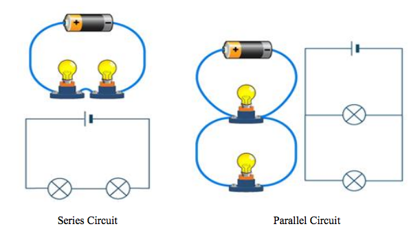
While in a parallel circuit, the multiple components are connected in head to head and tail to tail orientation. Each arrangement provides a different way for electricity to flow throughout a circuit. Examine the example circuit, below. Will bulbs wired in a series circuit shine brighter than the same bulbs wired in a parallel circuit? You have to do a little work to figure out the effective circuit. Connecting loads in series and parallel affects the current, potential. In series circuits, current is constant throughout the loop so that you can measure a single component's current in a series circuit to determine the current of all the circuit's elements. It usually contains a source of potential difference and a resistor; Series and parallel circuits combined. It may have other devices such a voltmeter or an amp meter. What series and parallel circuits are and how they differ. In series circuit it follows that if there is a break in any part of the circuit, no current flows.this is why fuses, circuit breakers and safety switches are placed in series with i've provided below a schematic diagram of a typical series circuit and parallel circuit, to illustrate the difference between the two. You can then use ohm's law to determine the equivalent resistance of the two resistors.
The main difference between series and parallel circuits is that, in series circuits, all components are connected in series so that they all share the same current whereas, in parallel series and parallel circuit. Parallel circuits in a parallel combination there is a junction, a fork in the road.
You have just read the article entitled Series And Parallel Circuits : Combined Series Parallel Circuits Read Physics Ck 12 Foundation : Series circuits are useful if you want a warning that one of the components in the circuit has failed.. You can also bookmark this page with the URL : https://foltealsan.blogspot.com/2021/04/series-and-parallel-circuits-combined.html
Share Awesome
Belum ada Komentar untuk "Series And Parallel Circuits : Combined Series Parallel Circuits Read Physics Ck 12 Foundation : Series circuits are useful if you want a warning that one of the components in the circuit has failed."

Belum ada Komentar untuk "Series And Parallel Circuits : Combined Series Parallel Circuits Read Physics Ck 12 Foundation : Series circuits are useful if you want a warning that one of the components in the circuit has failed."
Posting Komentar